By Allen Houtz1 and Doug Cooper
A select element receives two input signals and forwards one of them onward in the signal path. A low select, shown below to the left, passes the lowest of the two signals, while ahigh select, shown to the right, passes the larger value onward.
A select element can be implemented as a DCS or PLC function block, as a few lines of computer code, or as a simple hardware circuit. And while the elements above are using electrical current, they can also be designed to select between high and low voltage ordigital (discrete) counts.
The above pictures are not meant to imply that the selected output value has anything to do with signal location. If the 12 mA signal shown entering on the lower input were to drop down to 5 mA while the 7 mA input entering from the left side remained constant, then the low select output would be 5 mA while the high select output would be 7 mA.
Logic Permits Increased Sophistication
The simple select element enables decision-making logic to be included in a control strategy, which in turn provides a means for increasing strategy sophistication. One such example is to use a select element to construct an architecture designed to control to a maximum or minimum limit or constraint.
Another popular application, and the one explored here, is to employ a select as anoverride element in a ratio control architecture. In particular, we explore how a select override might be included in an air/fuel ratio combustion control strategy to enhance safety, limit emissions and maximize useful energy from fuel.
Ratio Strategy Without Override
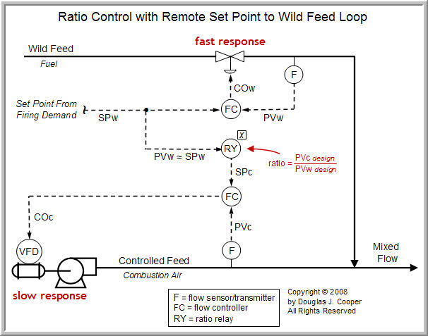
Before demonstrating the use of a select override, we consider a variation on our previously discussed ratio control of a metered-air combustion process. Shown below (click for a larger view) is a ratio architecture much like that used in the referenced article except here we choose to employ a ratio relay with remote input rather than a flow fraction controller.
In this design, the fuel mass flow rate is regulated by a flow controller whose set point, SPw, arrives as a firing demand from elsewhere in the plant. SPw might be generated, for example, by a controller adjusting the duct temperature downstream of a burner, the temperature of a heat transfer fluid exiting a furnace or the pressure in a steam header.
There is an implicit assumption in this architecture that the fuel mass flow rate closely tracks the firing demand set point, that is, PVw ≈ SPw. Thus, an integral term (e.g., PI control) is required in the wild feed flow control algorithm.
Since SPw is set elsewhere, we are not free to adjust fuel flow rate separately to maintain a desired air/fuel ratio. It is thus appropriately designated as the “wild feed” in this construction.
As SPw (and thus PVw) increases and decreases, a ratio relay shown in the control diagram multiplies the incoming signal by a design air/fuel ratio value (or in the general case, a controlled/wild feed ratio value) to compute the combustion air set point, SPc, for the controlled feed flow loop.
| Practitioner’s Note: A ratio controller architecture requires that the signal from each mass flow sensor/transmitter change linearly with flow rate. Thus, the signals from the wild stream process variable, PVw, and the controlled stream process variable, PVc, should increase and decrease in a straight-line fashion as the individual mass flow rates increase and decrease. If the flow sensor is not linear, additional computations (function blocks) must be included between the sensor and the ratio relay to transform the nonlinear signal into the required linear flow-to-signal relationship. |
If the fuel flow control loop and the combustion air control loop both respond quickly to flow commands COw and COc respectively, then the architecture above should maintain the desired air/fuel ratio even if the demand set point signal, SPw, moves rapidly and often.
Problem if the Combustion Air Loop is Slow
The diagram shows a valve as the final control element (FCE) adjusting the fuel mass flow rate, and a variable frequency drive (VFD) and blower assembly as the FCE adjusting the combustion air mass flow rate. Valves generally respond quickly to controller output signal commands, so we expect the fuel mass flow rate to closely track changes in COw.
In contrast, air blower assemblies vary in capability. Here we consider a blower that responds slowly to control commands, COc, relative to the valve (the time constant of the blower “process” is much larger than that of the valve).
While we desire that the mass flow rates of the two streams move together to remain in ratio, the different response times of the FCEs means that during a firing demand change (a change in SPw), the feed streams may not be matched at the desired air/fuel ratio for a period of time.
To illustrate, consider a case where the firing demand, SPw, suddenly increases. The fuel flow valve responds quickly, increasing fuel feed to the burner. The ratio relay will receive SPw and raise the set point of the combustion air mass flow rate, SPc, so the two streams can remain in ratio.
If the air blower response is slow, however, a fuel rich environment can temporarily develop. That is, there will be a period of time when we are below the desired 5% to 20% of excess air (below the 105% to 120% of theoretical or stoichiometric air) as we wait for the blower to ramp up and deliver more air to the burner.
If there is insufficient air for complete combustion, then carbon monoxide and partially burned fuel will appear in the exhaust stack. As such, we have a situation where we are wasting expensive fuel and violating environmental regulations.
◊ Solution 1: Detune the Fuel Feed Controller
One solution is to enter conservative or sluggish tuning values into the fuel feed controller. By detuning (slowing down) the wild feed control loop so it moves as slowly as the combustion air blower, the two feed streams will be able to track together and stay in ratio. We thus avoid creating the fuel rich environment as just described.
Unfortunately, however, we also have made the larger firing demand control system less responsive, and this diminishes overall plant performance. In some process applications, a slow or sluggish ratio control performance may be acceptable. In the particular case of combustion control, it likely is not.
◊ Solution 2: Use a Low Select Override
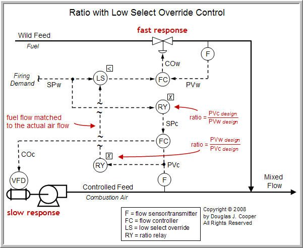
The addition of an override to our control architecture is shown below (click for a larger view). The diagram is the same as that above except a second ratio relay feeding a low select element has been included in the design.
The second ratio relay receives the actual measured combustion air mass flow rate, PVc, and computes a matching fuel flow rate based on the design air/fuel ratio. This “fuel flow matched to the actual air flow” value is transmitted to the low select element. As shown below, the low select element also receives the firing demand fuel flow rate, SPw, set elsewhere in the plant.
A low select element passes the lowest of the two input signals forward. In this case, if SPw is a fuel rate that exceeds the availability of combustion air required to burn it, the select element will override the demand signal and forward the lower “fuel flow matched to the actual air flow” signal.
The override strategy shown above thus ensures that the feed streams remain in ratio for a rapid increase in firing demand, SPw, but it has no effect when there is a rapid decrease in firing demand.
When SPw rapidly decreases, the fuel flow rate will respond quickly and we will be in a “lean” environment (too much combustion air) until the blower slows to match the decreased fuel rate. When there is more air than that needed for complete combustion, the extra nitrogen and unneeded oxygen absorb heat energy, decreasing the temperature of the flame and gases in the combustion zone.
So while the select override element has eliminated pollution concerns when firing demand rapidly increases, we produce a surplus of hot air that simply leaves the exhaust stack as lost profit when firing demand rapidly decreases. In effect, we have solved only half the air/fuel balance problem with a single select override element.
A Simulated Furnace Air/Fuel Ratio Challenge
To further our understanding of the select override in an air/fuel ratio strategy, we consider a furnace simulation (images shown below) available in commercial software. The furnace burns natural gas to heat a process liquid flowing through tubes in the fire box. Firing demand is determined by a temperature controller located on the process liquid as it exits the furnace.
Because the output of the firing demand temperature controller becomes the set point to the wild feed of the air/fuel ratio strategy, it is in fact a primary (or outer) controller in acascade control architecture. If the temperature of the process liquid is too hot (greater than set point), the firing demand controller seeks to reduce energy input. If the temperature is below set point, it seeks to add energy.
Unlike the example above, combustion air is the wild feed in this furnace simulation. Thus, when the firing demand temperature controller is in automatic (the cascade is enabled) set point changes are transmitted to the air flow controller. If the temperature controller is in manual, the set point of the combustion air flow controller must be entered manually by operations staff.
- Firing Demand in Manual
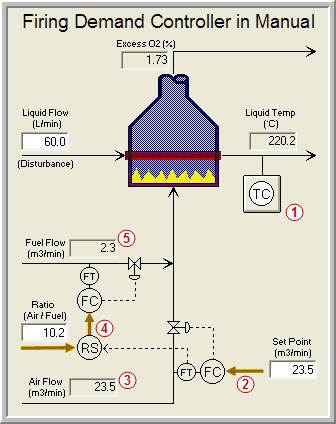
We first consider furnace operation when the firing demand temperature controller is in manual mode as shown below (click for a larger view).
Following the number labels on the above diagram:
| 1. | The firing demand temperature controller on the process liquid exiting the furnace is in manual mode. As such, it takes no control actions. |
| 2. | With the firing demand controller in manual, operations staff enter a set point (SP) into the combustion air flow controller. The controller adjusts the air flow valve to ensure the measured combustion air feed equals the SP value. |
| 3. | The display is in volume units (m3/min), though ratio controllers traditionally employ a mass flow basis (see Notes below). |
| 4. | Operations staff enter a desired air/fuel ratio into the ratio station (RS). The entered value is much like a set point. The ratio station receives the combustion air flow signal and forwards a fuel flow set point to maintain the desired ratio. |
| 5. | The flow controller adjusts the fuel valve to maintain the desired ratio. Here, the air/fuel ratio is: 23.5/2.3 = 10.2 |
| Notes: ▪ The fuel flow controller has its set point established by the signal from the ratio station (RS), which could be constructed, for example, by inverting the desired air/fuel ratio with a division function and then using a multiplying relay to compute a desired fuel flow rate. ▪ The flow transmitters for the combustion air and fuel rate must be linearized as discussed in the introductory ratio control architecture article. ▪ Ratio control traditionally uses a mass flow basis. The use of volumetric flow units implies that the air and fuel are delivered at fixed temperature and pressure, thus making the volume flows proportional to the mass flows. Alternatively, a sophisticated function could translate mass flows to volume flows for display purposes. An air/fuel ratio in mass units (kg for example) would have a different value from the volume ratio because of the difference in molecular weights for the two streams. |
- Firing Demand in Automatic
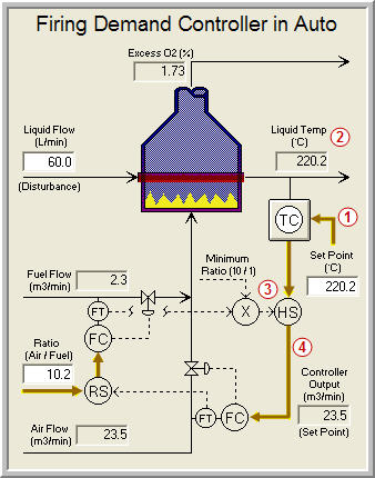
With operation steady, we switch the firing demand temperature controller to automatic as shown below (click for a larger view).
Following the number labels on the above diagram:
| 1. | The firing demand controller measures the temperature of the process liquid exiting the furnace (the measured process variable, PV), compares it to the set point (SP) value, and computes as its controller output signal an air feed rate set point. |
| 2. | In the figure above, the measured PV equals the SP of the temperature controller, so the air feed set point from the firing demand controller is the same as when it was in manual mode. |
| 3. | A high select element receives the air feed set point from the firing demand controller and a minimum permitted air feed set point based on the current flow of fuel. |
| 4. | The larger of the two air feed set points is forwarded by the high select element to the air flow controller, ensuring that there is always sufficient air to completely combust the fuel in the firebox. Because the firing demand controller generates an air feed set point that is above the minimum 10/1 ratio specified by the designers, then the high select element passes it onward to the combustion air flow controller. |
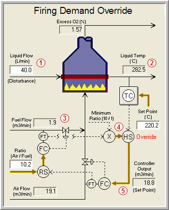
- Firing Demand Override
A process upset requires that the high select element override the firing demand controller as shown below (click for a larger view).
Following the number labels on the above diagram:
| 1. | The flow rate of the process liquid drops from 60 to 40 L/min, reducing the heat energy demand on the furnace. |
| 2. | As flow rate drops, the excess energy in the furnace raises the exit temperature of the process liquid. The measured PV temperature moves well above the SP, causing the firing demand controller to decrease energy input by rapidly lowering the set point to the air flow controller. |
| 3. | The current flow rate of fuel is 1.9 (actually 1.88 but the display has round off). |
| 4. | The minimum ratio that ensures enough air to complete combustion in the firebox of this furnace is a 10/1 ratio of air/fuel, or 1.88 x 10 = 18.8 m3/min. The high select element receives a combustion air feed rate from the firing demand controller that is below this minimum. |
| 5. | The high select element overrides the air flow set point from the firing demand controller and forwards the minimum 18.8 m3/min air flow sufficient for complete combustion. |
The first example in this article employed fuel as the wild feed. This second furnace example used combustion air as the wild feed. Yet in both cases, an override element was required to implemented a control strategy that enhanced safety, limited emissions and maximized the useful energy from fuel.
Cross-Limiting Ratio Control Strategy
If we were to increase the process liquid flow rate through the furnace, the firing demand controller would quickly ramp up the combustion air feed rate to provide more energy. Temporarily, there would be more air than that needed for complete combustion. That temporary surplus of hot air will carry its heat energy up and out the exhaust stack as lost profit.
So similar to the first example, a single select override element provides only half the solution depending on the direction that the upstream demand is moving.
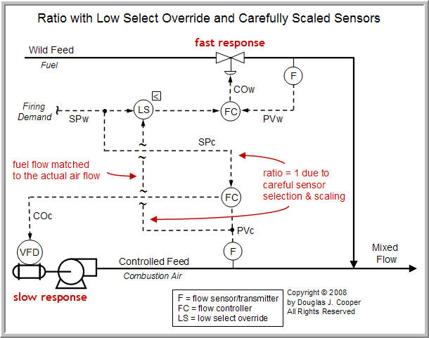
The next article presents the use of two select override elements in a cross-limiting ratio control strategy. While fairly complex, the cross limiting structure offers benefit in that it provides protection in an air/fuel ratio strategy both when firing demand is increasing anddecreasing.
We will simplify the diagrams in that article as shown below (click for a larger view) by assuming that the two linearized flow sensor/transmitters have been carefully scaled so that both signals at the desired air/fuel ratio are exactly one to one.
By careful sensor selection and scaling, we can maintain the “ratio with low select override” strategy as presented earlier in this article while eliminating the multiplying relays from our design. As long as we use control algorithms with an integrating term (PI or PID), the upstream demand signal becomes the set point for both controllers and the desired ratio will be maintained.
____
1. Allen D. Houtz
Consulting Engineer
Automation Systems Group
P.O. Box 884
Kenai, AK 99611
Email: ifadh@uaa.alaska.edu