Our control objective for the jacketed stirred reactor process is to minimize the impact on reactor operation when the temperature of the liquid entering the cooling jacket changes. We have previously explored the modes of operation and dynamic CO-to-PV behavior of the reactor. We also have established the performance of a single loop PI controller and a PID with CO Filter controller in this disturbance rejection application.
Here we consider a cascade architecture as a means for improving the disturbance rejection performance in the jacketed stirred reactor.
The Single Loop Jacketed Stirred Reactor
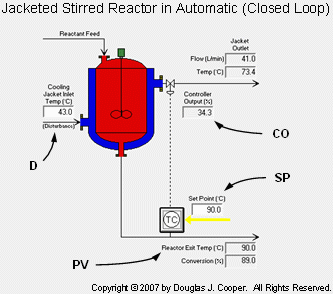
As shown in the process graphic below (click for large view), the reactor exit stream temperature is controlled by adjusting the flow rate of cooling liquid through an outer shell (or cooling jacket) surrounding the main vessel.
As labeled above for the single loop case:
CO = signal to valve that adjusts cooling jacket liquid flow rate (controller output, %)
PV = reactor exit stream temperature (measured process variable, oC)
SP = desired reactor exit stream temperature (set point, oC)
D = temperature of cooling liquid entering the jacket (major disturbance, oC)
The control objective is to maintain the reactor exit stream temperature (PV) at set point (SP) in spite of unmeasured changes in the temperature of cooling liquid entering the jacket (D).
We measure exit stream temperature with a sensor and transmit the signal to a temperature controller (the TC inside the circle in the diagram). After comparing SP to PV, the temperature controller computes and transmits a CO signal to the cooling jacket liquid flow valve.
As the valve opens and closes, the flow rate of liquid through the jacket increases and decreases. Like holding a hot frying pan under a water faucet, higher flow rates of cooling liquid remove more heat. Thus, a higher flow rate of cooling liquid through the jacket cools the reactor vessel, lowering the reactor exit stream temperature.
Problems with Single Loop Control
The single loop architecture in the diagram above attempts to achieve our control objective by adjusting the flow rate of cooling liquid through the jacket.
If the measured temperature is higher than set point, the controller signals the valve to increase cooling liquid flow by an appropriate percentage with the expectation that this will decrease reactor exit stream temperature accordingly.
A concern discussed in detail in this article is that the temperature of the cooling liquid entering the jacket (D) can change, sometimes rather quickly. This can disrupt reactor operation as reflected in the measured reactor exit stream temperature PV.
So reactor exit stream temperature PV is a function of two variables:
▪ cooling liquid flow rate, and
▪ the temperature of the cooling liquid entering the cooling jacket (D).
To explore this, we conduct some thought experiments:
Thought Experiment #1: Assume that the temperature of the cooling liquid entering the jacket (D) is constant over time. If the cooling liquid flow rate increases by a certain amount, the reactor exit stream temperature will decrease in a predictable fashion (and vice versa). Thus, a single loop structure should provide good temperature control performance.
Thought Experiment #2: Assume that the temperature of cooling liquid entering the jacket (D) starts rising over time. A warmer cooling liquid can carry away less heat from the vessel. If the cooling liquid flow rate is constant through the jacket, the reactor will experience less cooling and the exit stream temperature will increase.
Thought Experiment #3: Now assume that the temperature of cooling liquid entering the jacket (D) starts to rise at the same moment that the reactor exit stream temperature moves above set point. The controller will signal for a cooling liquid flow rate increase, yet because the cooling liquid temperature is rising, the heat removed from the reactor vessel can actually decrease. Until further corrective action is taken, the reactor exit stream temperature can increase.
As presented in Thought Experiment #3, the changing temperature of cooling liquid entering the jacket (a disturbance) can cause a contradictory outcome that can confound the controller and degrade control performance.
Cascade Control Improves Disturbance Rejection
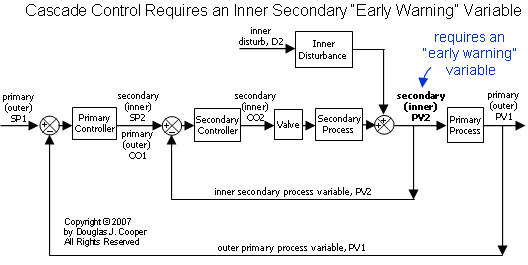
As we established in our study of the cascade control architecture, an essential element for success in a cascade (nested loops) design is the measurement and control of an “early warning” process variable, PV2, as illustrated in the block diagram below (click for a large view).
Since disruptions impact PV2 first, it provides our “early warning” that a disturbance is heading toward our outer primary process variable, PV1. The inner secondary controller can begin corrective action immediately. And since PV2 responds first to valve manipulations, disturbance rejection can begin before PV1 has been visibly impacted.
A Reactor Cascade Control Architecture
The thought experiments above highlight that it is problematic to control exit stream temperature by adjusting the cooling liquid flow rate.
An approach with potential for “tighter” control is to adjust the temperature of the cooling jacket itself. This provides a clear process relationship in that, if we seek a higher reactor exit stream temperature, we know we want a higher cooling jacket temperature. If we seek a lower reactor exit stream temperature, we want a lower cooling jacket temperature.
Because the temperature of cooling liquid entering the jacket changes, increasing cooling jacket temperature by a precise amount may mean decreasing the flow rate of cooling liquid a lot, decreasing it a little, and perhaps even increasing the flow rate a bit.
A “cheap and easy” proxy for the cooling jacket temperature is the temperature of cooling liquid exiting at the jacket outlet. Hence, we choose this as our inner secondary process variable, PV2, as we work toward the construction of a nested cascade control architecture.
Adding a temperature sensor that measures PV2 provides us the early warning that changes in D, the temperature of cooling liquid entering the jacket, are about to impact the reactor exit stream temperature, PV1.
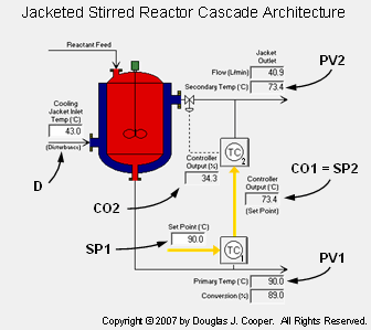
The addition of a second temperature controller (TC2) completes construction of a jacketed reactor control cascade as shown in the graphic below (click for a large view).
Now, our inner secondary control loop measures the temperature of cooling liquid exiting at the jacket outlet (PV2) and sends a signal (CO2) to the valve adjusting cooling jacket flow rate. The valve increases or decreases the flow rate of cooling liquid if the jacket temperature needs to fall or rise, respectively.
Our outer loop maintains reactor exit stream temperature (our process variable of primary interest and concern) as PV1. Note in the graphic above that the controller output of our primary controller, CO1, becomes the set point of our inner secondary controller, SP2.
If PV1 needs to rise, the primary controller signals a higher set point for the jacket temperature (CO1 = SP2). The inner secondary controller then decides if this means opening or closing the valve and by how much.
Thus, variations in the temperature of cooling liquid entering the jacket (D) are addressed quickly and directly by the inner secondary loop to the benefit of PV1.
The cascade architecture variables are identified on the above graphic and listed below:
PV2 = cooling jacket outlet temperature is our “early warning” process variable (oC)
CO2 = controller output to valve that adjusts cooling jacket liquid flow rate (%)
SP2 = CO1 = desired cooling jacket outlet temperature (oC)
PV1 = reactor exit stream temperature (oC)
SP1 = desired reactor exit stream temperature (oC)
D = temperature of cooling liquid entering the jacket (oC)
The inner secondary PV2 (cooling jacket outlet temperature) is a proper early warning process variable because:
▪ PV2 is measurable with a temperature sensor.
▪ The same valve used to manipulate PV1 also manipulates PV2.
▪ The same disturbance that is of concern for PV1 also disrupts PV2.
▪ PV2 responds before PV1 to the disturbance of concern and to valve manipulations.
Reactor Cascade Block Diagram
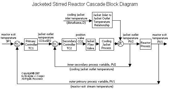
The jacketed stirred reactor block diagram (click for a large view) for this nested cascade architecture is shown below.
As expected for a nested cascade, this architecture has:
▪ two controllers (an inner secondary and outer primary controller)
▪ two measured process variable sensors (an inner PV2 and outer PV1)
▪ only one valve (to adjust cooling liquid flow rate)
Tuning a Cascade
With a cascade architecture established, we apply our implementation recipe for cascade control and explore the disturbance rejection capabilities of this structure.


