In our study of the derivative mode of a PID controller, we explored how noise or random error in the measured process variable (PV) can degrade controller performance.
As discussed in that article, derivative action can cause the noise in the PV measurement to be reflected and amplified in the controller output (CO) signal, producing “chatter” in the final control element (FCE). This extreme control action will increase the wear on a mechanical FCE (e.g., a valve) and lead to increased maintenance needs.
Sources of Noise
Random behavior in the PV measurement arises because of signal noise and process noise.
Signal noise tends to have higher frequency relative to the characteristic dynamics of process control applications (i.e., processes with streams comprised of liquids, gases, powders, slurries and melts). Sources of signal noise include:
▪ electrical interference
▪ jitter (clock related irregularities such as variations in sample spacing)
▪ quantizing of signal samples into overly-broad discrete “buckets” from low resolution or improperly specified instrumentation (e.g. too-large measurement span relative to operating range).
Process noise tends to be lower in frequency. This category borders on the philosophical as to what constitutes a disturbance to be controlled versus noise to be filtered.
Bubbles and splashing that randomly corrupts liquid pressure drop measurements is an example of process noise that might benefit from filtering.
A less clear candidate for filtering is a temperature measurement in a poorly-mixed vessel. The mixing patterns can cause lower-frequency random variations in the temperature signal that are unrelated to changes in the bulk vessel temperature.
It is important to emphasize that before we try to filter away a problem, we should first work to understand the source of the random error. Rather than “fix” the noise by hiding it with additional or modified algorithms, we should attempt to reduce or eliminate the problem through normal engineering and maintenance practices.
The Filtered Signal
The plot below shows the random behavior of a raw (unfiltered) PV signal and the smoother trace of a filtered PV signal.
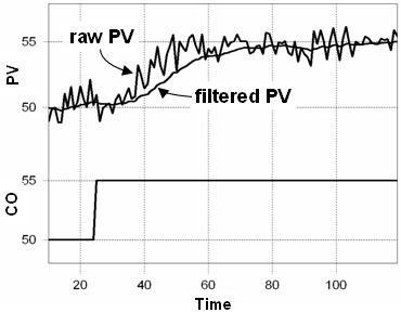
As the above plot illustrates, a filter is able to receive a noisy signal and yield a signal with reduced random variation. A “better” filter design is one that decreases the random variation while retaining more of the true dynamic information of the original signal.
Filters can be analog (hardware) or digital (software); high, low or band pass; linear or nonlinear; designed in the time, Z-transform or frequency domain; and much more. Filters can collect and process data at a rate faster than the control loop sample time, so many data points can go into a single PV sample forwarded to the controller.
Clearly, filter design is a substantial topic. In these articles we offer only an introduction to the basic methods and ideas.
Filters Add Delay
The filtered signal in the plot above, though perhaps visually appealing, clearly lags behind the actual dynamic response of the unfiltered signal. More specifically, the filtered signal has an increased dead time and time constant relative to the behavior of the actual process.
Signal filters offer benefit in process control applications because they can temper the large CO moves caused by derivative action of noisy PV measurements.
Yet they add delay in sensing the true state of a process, and this has negative consequences in that as delay increases, the best achievable control performance decreases.
The design challenge is to find the careful balance between signal smoothing and information delay to achieve the controller performance we desire for our application.
External Filters in Control
As shown below (click for large view), there are three popular places to put external filters in the feedback loop. By “external,” we mean that the filters are designed, installed and maintained separately from the controller.
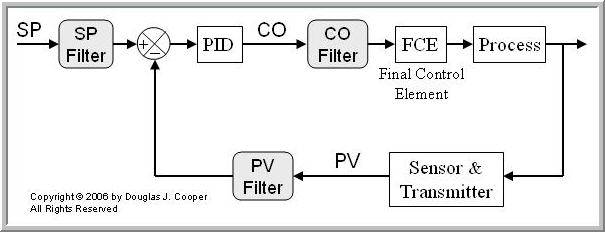
Internal filters that are part of the controller architecture itself are introduced later in this article.
• Set Point Filters
Set point filters are not associated with the noisy PV problem, but are included here to make the discussion general.
A set point filter takes a step change in SP, and as shown below, forwards a smooth transition signal to the controller.
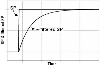
SP filters do not influence the disturbance rejection (regulatory) performance of a controller. Hence, these filters permit a controller to be tuned aggressively to reject disturbances, yet the smoothed SP transition results in a moderate set point tracking (servo) performance from this same aggressive controller.
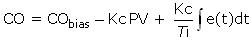
SP filters are also used to limit overshoot at the top of a set point ramp or step change. If this is our design objective, an alternative is to eliminate the filter and employ a controller that uses proportional on PV rather than proportional on error. For example (compare to PI with proportional on error here):
We will explore methods to limit overshoot in more detail in a future article.
Finally, and unfortunately, SP filters are occasionally used as a bandage to mask the fact that a controller is simply poorly designed and/or tuned. We all recognize that this is a practice to be avoided.
• PV Filters
Signal filters are frequently placed between the sensor transmitter and the controller (or more likely, the multiplexer feeding the controller). In process control applications, these filters should be analog (hardware) devices designed specifically to minimize high frequency electrical interference.
While measurement noise does degrade derivative action in that it leads to chatter in the CO signal, this “noise leads to CO chatter” effect is very modest for proportional action. And interestingly, integral action is unaffected by noise because the constant summing of error literally averages the random variations in the signal.
Since filtering adds delay and this hurts best possible control performance, and because noise is not an issue for proportional and integral action, it is generally poor practice to filter the PV signal external to the controller for anything beyond electrical interference.
The preferred approach is to selectively filter only that signal destined for the derivative computation. This moves the filter inside the controller architecture as discussed below.
• CO Filters
While PV filters smooth the signal feeding the controller, CO filters smooth the noise or “chatter” in the CO signal sent to the final control element. Even if PV signal noise does not appears to cause performance problems, a CO filter can offer potential benefits as it reduces fluctuations in the controller output and this reduces wear on the FCE.
If a noisy PV is an issue in our controller, our first attempts should be to locate and correct the problem. If after that exercise, our decision is to design and implement a filter in our feedback loop, CO filters are attractive alternatives.
The design of a CO filter can be integrated as part of the loop tuning exercise. We will see in a later article how we can integrate an external CO filter into a unified “PID with CO Filter” form, and then use our controller design recipe to tune what is essentially a four mode controller.
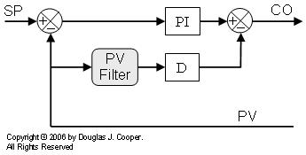
Internal Filters in Control
For feedback control, filtering need only be applied to the signal feeding the derivative term. As stated before, noise does not present a problem for proportional and integral action. These elements will perform best without the delay introduced from a signal filter.
When we selectively filter just that signal feeding the derivative calculation, the filter becomes part of the controller architecture. Hence, we can still use our design recipe, though the correlations for tuning this four mode form are different from the four mode “PID with CO Filter” form mentioned above.
There are two common architectures that are identical in capability, though different in presentation.
As shown below, we filter the PV signal before feeding it to the derivative mode of the PID algorithm for computation:
We can also compute the derivative action with the noisy signal and then filter the computed result:
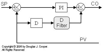
If the same filter form is used (e.g., first-order), we can show mathematically that both options above are identical.
As it turns out, many commercial controllers use this internal derivative filtering form where they implement a first-order filter and fix the filter time at one-tenth of the derivative time value.