By Allen Houtz1 and Doug Cooper
A ratio control strategy can play a fundamental role in the safe and profitable operation of fired heaters, boilers, furnaces and similar fuel burning processes. This is because the air-to-fuel ratio in the combustion zone of these processes directly impacts fuel combustion efficiency and environmental emissions.
A requirement for ratio control implementation is that both the fuel feed rate and combustion air feed rate are measured and available as process variable (PV) signals. Shown below (click for a large view) is a conceptual air/fuel ratio control strategy.

In this representative architecture, the fuel flow rate is adjusted to maintain the temperature of a heat transfer fluid exiting a furnace. On other processes, fuel flow rate might be adjusted to maintain the pressure in a steam header, the duct temperature downstream of the burner, or similar variable that must be regulated for efficient operation.
The combustion air feed rate is then adjusted by a flow fraction (ratio) controller to maintain a desired air/fuel ratio. While a simple sensor and valve is shown above, we will expand and modify this conceptual architecture as we progress in this discussion because:
▪ The final control element (FCE) for the combustion air stream, rather than being a valve, is more commonly a variable speed blower, perhaps with adjustable dampers or louvers.
▪ Measuring combustion air flow rate is challenging and can involve measuring a pressure drop across a portion of the combustion gas exhaust flow path.
▪ In different applications, the air flow rate can be the wild feed while fuel flow rate is the controlled feed.
▪ Stack gas analyzers add value and sophistication as they monitor the chemistry associated with combustion efficiency and environmental emissions.
Why Air/Fuel Ratio is Important
In combustion processes, air/fuel ratio is normally expressed on a mass basis. We get maximum useful heat energy if we provide air to the combustion zone at a mass flow rate (e.g., lb/min, Kg/hr) that is properly matched to the mass flow rate of fuel to the burner.
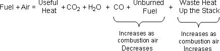
Consider this generic equation for fuel combustion chemistry:
Where:
CO2 = carbon dioxide
CO = carbon monoxide
H2O = water
Air = 21% oxygen (O2) and 79% nitrogen (N2)
Fuel = hydrocarbon such as natural gas or liquid fuel oil
Air is largely composed of oxygen and nitrogen. It is the oxygen in the air that combines with the carbon in the fuel in a highly energetic reaction called combustion. When burning hydrocarbons, nature strongly prefers the carbon-oxygen double bonds of carbon dioxide and will yield significant heat energy in an exothermic reaction to achieve this CO2 form.
Thus, carbon dioxide is the common green house gas produced from the complete combustion of hydrocarbon fuel. Water vapor (H2O) is also a normal product of hydrocarbon combustion.
| Aside: nitrogen oxide (NOx) and sulfur oxide (SOx) pollutants are not included in our combustion chemistry equation. They are produced in industrial combustion processes principally from the nitrogen and sulfur originating in the fuel. As the temperature in the combustion zone increases, a portion of the nitrogen in the air can also convert to NOx. NOx and SOx combustion chemistry is beyond the scope of this article but a detailed discussion can be found here. |
Too Little Air Increases Pollution and Wastes Fuel
The oxygen needed to burn fuel comes from the air we feed to the process. If the air/fuel ratio is too small in our heater, boiler or furnace, there will not be enough oxygen available to completely convert the hydrocarbon fuel to carbon dioxide and water.
A too-small air/fuel ratio leads to incomplete combustion of our fuel. As the availability of oxygen decreases, noxious exhaust gases including carbon monoxide will form first. As the air/fuel ratio decreases further, partially burned and unburned fuel can appear in the exhaust stack, often revealing itself as smoke and soot. Carbon monoxide, partially burned and unburned fuel are all poisons whose release is regulated by the government (the Environmental Protection Agency in the USA).
Incomplete combustion also means that we are wasting expensive fuel. Fuel that does not burn to provide useful heat energy, including carbon monoxide that could yield energy as it converts to carbon dioxide, literally flows up our exhaust stack as lost profit.
Too Much Air Wastes Fuel
The issue that makes the operation of a combustion process so interesting is that if we feed too much air to the combustion zone (if the air/fuel ratio is too high), we also waste fuel, though in a wholly different manner.
Once we have enough oxygen available in the burn zone to complete combustion of the hydrocarbon fuel to carbon dioxide and water, we have addressed the pollution portion of our combustion chemistry equation. Any air fed to the process above and beyond that amount becomes an additional process load to be heated.
As the air/fuel ratio increases above that needed for complete combustion, the extra nitrogen and unneeded oxygen absorb heat energy, decreasing the temperature of the flame and gases in the combustion zone. As the operating temperature drops, we are less able to extract useful heat energy for our intended application.
So when the air/fuel ratio is too high, we produce a surplus of hot air. And this hot air simply carries its heat energy up and out the exhaust stack as lost profit.
Theoretical (Stoichiometric) Air
The relationship between the air/fuel ratio, pollution formation and wasted heat energy provides a basis for control system design. In a meticulous laboratory experiment with exacting measurements, perfect mixing and unlimited time, we could determine the precise amount of air required to just complete the conversion of a hydrocarbon fuel to carbon dioxide and water. This minimum amount is called the “theoretical” or “stoichiometric” air.
Unfortunately, real combustion processes have imperfect mixing of the air with the fuel. Also, the gases tend to flow so quickly that the air and fuel mix have limited contact time in the combustion zone. As such, if we feed air in the exact theoretical or stoichiometric proportion to the fuel, we will still have incomplete combustion and lost profit.
Real burners generally perform in a manner similar to the graph below. The cost associated with operating at increased air/fuel ratios is the energy wasted in heating extra oxygen and nitrogen. Yet as the air/fuel ratio is decreased, losses due to incomplete combustion and pollution generation increase rapidly.
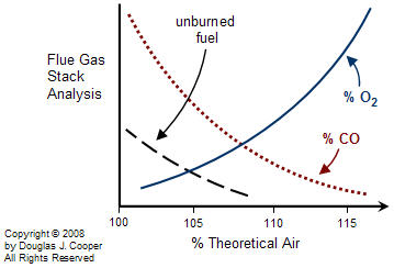
For any particular burner design, there is a target air/fuel ratio that balances the competing effects to minimize the total losses and thus maximize profit. As the graph above suggests (note that there is no scale on the vertical axis), a gas or liquid fuel burner generally balances losses by operating somewhere between 105% to 120% of theoretical air. This is commonly referred to as operating with 5% to 20% excess air.
Sensors Should be Fast, Cheap and Easy
Fired heaters, boilers and furnaces in processes with streams composed of gases, liquids, powders, slurries and melts are found in a broad range of manufacturing, production and development operations. Knowing that the composition of the fuel, the design of the burners, the configuration of the combustion zone, and the purpose of the process can differ for each implementation hints at a dizzying array of control strategy design and tuning possibilities.
To develop a standard control strategy, we require a flexible method of measuring excess air so we can control to a target air/fuel ratio. As discussed in this article, we normally seek sensors that are reliable, inexpensive, easy to install and maintain, and quick to respond. If we cannot get these qualities with a direct measurement of the process variable (PV) of interest, then an effective alternative is to measure a related variable if it can be done with a “fast, cheap and easy” sensor option.
Excess air is an example of a PV that is very challenging to directly measure in the combustion zone, yet oxygen and energy content in the stack gases is an appropriate alternative. As it turns out, operating with 5% to 20% excess air equates to having about 1% to 3% oxygen by volume in the stack gases.
Measuring the Stack Gases
By measuring exhaust stack gas composition, we obtain information we need to properly monitor and control air/fuel ratio in the combustion zone. Stack analyzers fall into two broad categories:
▪ Dry Basis Extractive Analyzers pull a gas sample from the stack and cool it to condense the water out of the sample. Analysis is then made on the dry stack gas.
▪ Wet Basis In Situ Analyzers are placed in very close proximity to the stack. The hot sample being measured still contains the water vapor produced by combustion, thus providing a wet stack gas analysis.
A host of stack gas (or flue gas) analyzers can be purchased that measure O2. The wet basis analyzers yield a lower oxygen value than dry basis analyzers by perhaps 0.3% – 0.5% by volume.
Instruments are widely available that also include a carbon monoxide measurement along with the oxygen measurement. A common approach is to pass the stack gas through a catalyst chamber and measure the energy released as the carbon monoxide and unburned fuel converts to carbon dioxide. The analyzer results are expressed as an equivalent percent CO in the sample. The single number, expressed as a CO measurement but representing fuel wasted because of insufficient air, simplifies control strategy design and process operation.
With a measurement of O2 and CO (representing all lost fuel) in the stack of our combustion process, we have critical PV measurements needed to implement an air/fuel ratio control strategy. Note that it is the responsibility of the burner manufacturer and/or process design staff to specify the target set point values for a particular combustion system prior to controller tuning.
Air Flow Metering
Combustion processes generally have combustion air delivered in one of three ways:
▪ A forced draft process uses a blower to feed air into the combustion zone.
▪ An induced draft process has a blower downstream of the burner that pulls or draws air through the combustion zone.
▪ A natural draft process relies on the void left as hot exhaust gases naturally rise up the stack to draw air into the combustion zone.
For this discussion, we assume a blower is being used to either force or induce combustion air feed because natural draft systems are not appropriately designed for active air flow manipulation.
Even with a blower, measuring the air feed rate delivered at low pressure through the twists and turns of irregular ductwork and firebrick is not cheap or easy. A popular alternative is to measure the pressure drop across some part of the exhaust gas stream. The bulk of the exhaust gas is nitrogen that enters with the combustion air. As long as the air/fuel ratio adjustments are modest, the exhaust gas flow rate will track the combustion air feed rate quite closely.
Thus, a properly implemented differential pressure measurement is a “fast, cheap and easy” method for inferring combustion air feed rate. The figure below (click for a large view) illustrates such a measurement across a heat transfer section and up the exhaust stack.
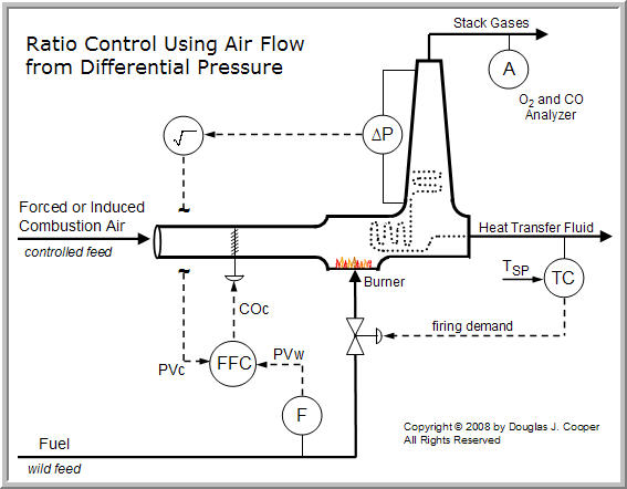
Also shown is that the controller output signal from the flow fraction (ratio) controller, COC, adjusts louvers to modulate the flow through the combustion zone. As the louvers open and close to permit more or less flow, the differential pressure measurement will increase or decrease, respectively.
As discussed in the ratio controller architecture article, the signal from the wild and controlled flow sensors must change linearly with flow rate. The differential pressure transmitter connected across a portion of the exhaust gas path becomes a linear gas flow sensor by recognizing that total gas flow, F, is proportional to the square root of the pressure differential (∆P), or  . Thus, the controlled feed process variable signal, PVC, is linear with flow when the square root of the differential pressure signal is extracted as shown in the diagram.
| Practitioner’s Note: The differential pressure measurement must not be connected across the portion of the gas flow path that includes the adjustable louvers. Each change in louver position changes the F vs. ∆P relationship. Success would require that during calibration, we somehow determine a different coefficient a for each louver position. This unrealistic task is easily avoided by proper location of the differential pressure taps.Calibrating the differential pressure signal to a particular air feed rate is normally achieved while the fired heater, boiler or furnace is operating with the air/fuel ratio controller in manual mode. The maximum or full scale differential pressure calibration is determined by bringing the fuel flow firing rate to maximum (or as close as practical) and then adjusting the air feed flow rate until the design O2 level is being measured in the stack gas.The differential pressure being measured by these sensors is very small and the exhaust gas contains water vapor that can condense in sensing lines. Even one or two inches of condensate in one side of the differential pressure transmitter can dramatically corrupt the measurement signal. |
Choosing Air or Fuel for Firing Rate Control
With a means of measuring both the combustion air flow and the fuel flow, and with a stack analyzer to permit calibration and monitoring, we can implement the simple air/fuel ratio control as shown in the diagram above.
Because it can be measured accurately, fuel feed rate is a popular choice for the firing rate control variable. Yet in certain applications it is more desirable to employ the combustion air flow rate in this capacity.
If fuel is the firing rate control variable, a rapid increase in firing rate with air following behind in time will lead to incomplete combustion as discussed above. On the other hand, if air is made the firing rate control variable, a rapid decrease in firing rate will lead to the same situation.
We study this issue in another article using a commercial furnace simulation. We focus on the benefits of a select override element to enhance safety, limit emissions and maximize useful energy from fuel.
____
1. Allen D. Houtz
Consulting Engineer
Automation Systems Group
P.O. Box 884
Kenai, AK 99611
Email: ifadh@uaa.alaska.edu