At the start of a recent Practical Process Control workshop, I asked the attendees what the “D” in PID stood for. One fellow immediately shouted from the back of the room, “Disaster?” Another piped in, “How about Danger?” When the laughter died down, another emphatically stated, “D is for Do not use.” This one got a good laugh out of me. I had not heard it before and thought it was perfect. And here’s why…
Benefits and Drawbacks
Derivative action has its largest influence when the measured process variable (PV) is changing rapidly (when the slope of the PV trace is steep).
The three terms of a properly tuned PID controller thus work together to provide a rapid response to error (proportional term), to eliminate offset (integral term), and to minimize oscillations in the PV (derivative term).
While this sounds great in theory, unfortunately, there are serious drawbacks to including derivative action in our controller.
We have discussed how challenging it can be to balance two interacting tuning parameters for PI control.
A PID controller has three tuning parameters (three modes) that all interact and must be balanced to achieve a desired performance. It is often not at all obvious which of the three tuning parameters must be adjusted to correct behavior if performance is considered to be undesirable.
Trial and error tuning is hopeless for any but the most skilled practitioner. Fortunately, our tuning recipe provides a quick route to a safe and profitable PID performance.
A second disadvantage relates to the uncertainty in the derivative computation for processes that have noise in the PV signal.
PID Controller Form
For discussion purposes in this article, we use the Dependent, Ideal (Non-interacting) form:
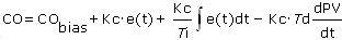
Nomenclature and tuning correlations for conservative, moderate and aggressive performance are presented here.
As discussed in this article, the various PID algorithms forms provide identical performance if each algorithm is matched to its proper tuning correlations. Hence, the observations and conclusions presented below are general in nature and are not specific to a particular algorithm form.
Derivative Action Dampens Oscillations
The plot below shows the impact of derivative action on set point response performance. Because noise in the PV signal can impact performance, an idealized noise-free simulation was used to create the plot.
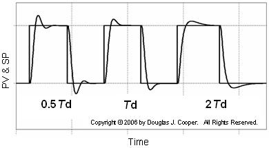
The plot shows the PV response to three pairs of set point (SP) steps. The middle response shows the base case performance of a PID controller tuned using the aggressive correlations referenced above.
For the set point steps to the right and left of the base case, the derivative time, Td, is adjusted while the controller gain, Kc, and reset time, Ti, are kept constant. This let’s us isolate the impact of derivative time on performance.
It is apparent that when derivative action is cut in half to the left in the plot, the oscillating nature of the response increases. And when Td is doubled to the right, the increased derivative action inhibits rapid movement in the PV, causing the rise time and settling time to lengthen.
We saw in this tuning map from the article on interacting tuning parameters for PI controllers that with only two tuning parameters, performance response plots could look similar.
With the addition of Td, we now have a three dimensional tuning map with a great many similar-looking plots. If we are unhappy with our controller performance, knowing which parameter to adjust and by how much borders on the impossible. With three mode PID control, the orderly approach of our tuning recipe becomes fundamental to success.
Measurement Noise Leads to Controller Output “Chatter”
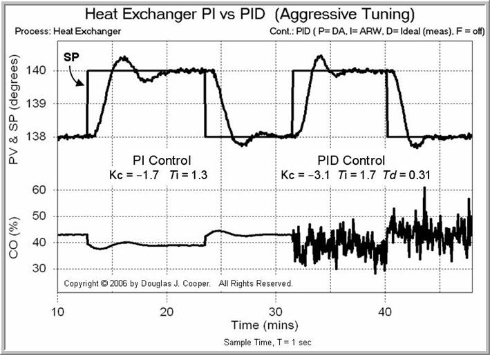
As discussed in more detail in the PID control of the heat exchanger study and summarized here, the side-by-side comparison of PI vs PID control (click for large view) shown below illustrates one unwelcome result of adding derivative action to our controller.
The CO signal trace along the bottom of the plot clearly changes when the derivative term is added. Specifically, derivative action causes the noise (random error) in the PV signal to be amplified and reflected in the controller output.
The reason for this extreme CO action or “chatter” is illustrated below (click for large view). As indicated in the plot, a noisy PV signal produces conflicting derivatives as the slope appears to dramatically alternate direction at every sample.
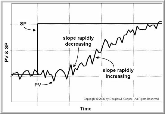
The consequence of a PV that repeatedly changes from “rapidly increasing slope” to “rapidly decreasing slope” is a derivative term that computes a series of large, alternating CO actions.
The ultimate impact of this alternating derivative computation on the total CO depends on the size of Td (the weight given to the derivative term). As Td grows larger, the “chatter” in the CO signal grows in response.
In any event, extreme control action will increase the wear on a mechanical final control element and lead to an increase in maintenance costs.
Larger Noise Means Larger Problems
The plot below (click for large view) shows a more subtle problem that measurement noise can cause with derivative action. In particular, this problem arises when the level of operation is near a controller output constraint (either the maximum or minimum CO).
The PID tuning values in the plot are constant throughout the experiment. As indicated on the plot, measurement noise is increased in increments across three set point tracking tests.
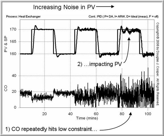
As long as measurement noise causes the derivative to alternate equally between suddenly increasing and suddenly decreasing, and the controller output can reflect this “equality in randomness” unimpeded, then controller performance is reasonably consistent in spite of increasing noise in the PV signal.
If a constraint inhibits the controller output from the “equality in randomness” symmetry, causing it to become skewed or off center, then controller performance degrades.
This is illustrated in the right most set point steps above. For this case, the controller output signal becomes so active that it repeatedly hits the minimum CO value. By constraining CO, the controller output loses its symmetry, causing the PV to wander.
What’s the Solution?
One solution is to include a signal filter somewhere in the PID loop. There are several possible locations, a half dozen candidate filter algorithms, and choice of a hardware or software implementation. We explore filtering enough to see big-picture concepts and the potential benefits, though we will by no means exhaust the topic.